Motherboard Overview
Introduction
Section titled “Introduction”This chapter introduces the Gigabyte B850 AORUS Elite WiFi7 motherboard before any components are installed.
The motherboard is the central connection point for the CPU, memory, SSD, GPU, case wiring, fans, USB ports, audio, networking, and power supply cables. Understanding the board layout before assembly reduces the risk of bent pins, misplaced memory, incorrect front-panel wiring, and inaccessible connectors after the board is installed in the case.
Purpose
Section titled “Purpose”Identify the motherboard sockets, slots, headers, buttons, and diagnostic indicators that will be used during this build.
Use the connector and cable reference for a consolidated list of the headers and cable rules used by this build.
Estimated Time
Section titled “Estimated Time”20-30 minutes.
Difficulty
Section titled “Difficulty”Beginner.
Required Tools
Section titled “Required Tools”- Gigabyte B850 AORUS Elite WiFi7 motherboard.
- Motherboard box or anti-static bag.
- Motherboard manual or digital reference.
- Bright lighting.
- Phone or camera for reference photos.
Warnings
Section titled “Warnings”- Keep the motherboard on its cardboard box or anti-static bag until it is installed.
- Do not touch the AM5 socket contacts.
- Do not place the motherboard on carpet, fabric, metal tools, screws, or loose cables.
- Do not connect PSU power cables while reviewing the board layout.
- Do not force any connector. Most headers are keyed or shaped for one orientation.
- Confirm the motherboard revision before using diagrams, BIOS files, or support downloads.
Step-by-Step Instructions
Section titled “Step-by-Step Instructions”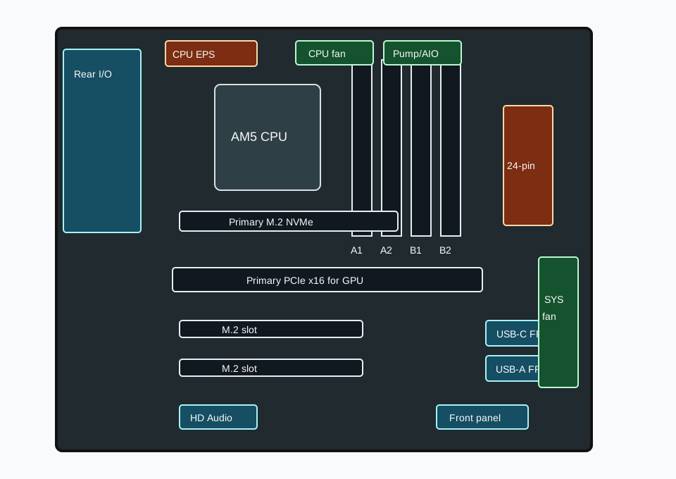
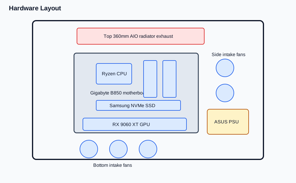
- Place the motherboard box on a stable table.
- Place the motherboard on top of the box with the rear I/O ports facing left.
- Locate the AM5 CPU socket in the upper centre of the board.
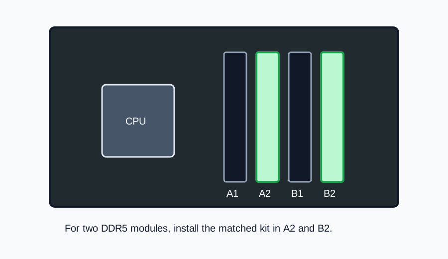
- Locate the four DDR5 DIMM slots to the right of the CPU socket.
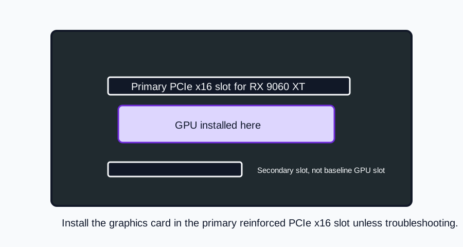
- Locate the top PCIe x16 slot for the graphics card.
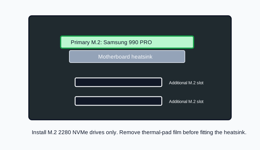
- Locate the three M.2 slots:
M2A_CPU,M2B_CPU, andM2C_SB. - Locate the 24-pin ATX power connector on the right edge of the board.
- Locate the 8-pin and 4-pin CPU power connectors at the top-left edge of the board.
- Locate the CPU, pump, and system fan headers.
- Locate the bottom-edge case headers: front panel, front audio, USB, RGB, TPM, reset, and Clear CMOS.
- Locate the rear I/O Q-Flash Plus button and the dedicated rear I/O port area.
- Locate the onboard power button, reset button, and debug LEDs.
- Take a photo of the board layout before installing components. Use it later when the board is inside the case.
Board Identity
Section titled “Board Identity”| Item | Detail |
|---|---|
| Model | Gigabyte B850 AORUS Elite WiFi7 |
| Chipset | AMD B850 |
| Socket | AMD AM5 |
| Form factor | ATX, 30.5cm x 24.4cm |
| Memory type | DDR5 |
| Operating system target | Windows 11 64-bit |
| Network | 2.5GbE LAN and Wi-Fi 7 |
Main Installation Areas
Section titled “Main Installation Areas”| Area | Label or location | Used for |
|---|---|---|
| CPU socket | Socket AM5 |
AMD Ryzen 7 7800X3D installation. |
| Memory slots | DDR5_A1, DDR5_A2, DDR5_B1, DDR5_B2 |
DDR5 memory installation. Use DDR5_A2 first; for two modules use the recommended dual-channel slots. |
| Primary GPU slot | PCIEX16 |
Gigabyte Radeon RX 9060 XT Gaming OC 16GB. |
| Primary M.2 slot | M2A_CPU |
Preferred boot SSD slot. With Ryzen 7000 CPUs, this slot supports PCIe 5.0 x4/x2 SSDs. |
| Secondary M.2 slot | M2B_CPU |
Additional NVMe SSD. With Ryzen 7000 CPUs, this slot supports PCIe 4.0 x4/x2 SSDs. |
| Chipset M.2 slot | M2C_SB |
Additional NVMe SSD through the chipset. Supports PCIe 4.0 x4/x2 SSDs. |
| SATA ports | SATA3 0/1/2/3 |
Optional 2.5-inch or 3.5-inch SATA drives. Not required for the selected NVMe-only build. |
Power Connectors
Section titled “Power Connectors”| Connector | Purpose | Notes |
|---|---|---|
ATX |
24-pin motherboard power | Connect the PSU 24-pin motherboard cable. |
12V_2X4 |
8-pin CPU power | Required for CPU power. |
12V_2X2 |
4-pin CPU auxiliary power | Connect if the PSU cable set provides it cleanly. Do not force cable routing. |
The system will not start correctly if CPU power is missing. Connect motherboard power only after the CPU, memory, SSD, cooler, and case placement are ready.
Fan and Pump Headers
Section titled “Fan and Pump Headers”| Header | Purpose in this build |
|---|---|
CPU_FAN |
CPU cooler fan signal or radiator fan group, depending on the cooler cable mode used. |
CPU_OPT |
Optional CPU fan or cooler-related secondary connection. |
SYS_FAN1, SYS_FAN2, SYS_FAN3 |
Case fans. |
FAN4_PUMP |
System fan or water-cooling pump header. Useful for pump or AIO-related wiring when needed. |
All fan headers are 4-pin. Configure fan and pump behaviour later through BIOS Smart Fan 6 after the system posts successfully.
Case and Front I/O Headers
Section titled “Case and Front I/O Headers”| Header | Purpose |
|---|---|
F_PANEL |
Case power switch, reset switch, power LED, drive activity LED, speaker, and chassis intrusion wiring. |
F_AUDIO |
Front-panel HD audio cable. |
FU3C_20G |
Front USB-C header with USB 3.2 Gen 2x2 support. |
FU3A_5G |
Front USB 3.2 Gen 1 header. |
FUSB_1, FUSB_2 |
USB 2.0 headers. |
F_HDMI |
Internal HDMI output for an in-case display panel. Not required for the base build. |
SPI_TPM |
Optional discrete TPM module. Not required because the platform supports firmware TPM. |
RST |
Reset jumper with configurable function. |
CLR_CMOS |
Clear CMOS jumper for resetting BIOS settings. |
Use the included Gigabyte G Connector if it makes front-panel wiring easier. Do not guess front-panel polarity for LED connectors; check the case cable labels and motherboard manual.
RGB Headers
Section titled “RGB Headers”| Header | Purpose |
|---|---|
ARGB_V2_1, ARGB_V2_2, ARGB_V2_3 |
3-pin addressable RGB Gen2 LED devices. |
LED_C |
4-pin RGB LED strip devices. |
Do not connect 3-pin ARGB devices to a 4-pin RGB header. The voltage and pin layout are different.
Rear I/O Overview
Section titled “Rear I/O Overview”The rear I/O area includes:
- DisplayPort output from the CPU integrated graphics path.
- Q-Flash Plus button.
- USB 2.0 ports.
- USB Type-C port with USB 3.2 Gen 2 support.
- USB 3.2 Gen 1 ports.
- RJ-45 2.5GbE LAN.
- USB 3.2 Gen 2 Type-A ports.
- Wi-Fi antenna connectors.
- Audio jacks and optical S/PDIF output.
Use the dedicated GPU display outputs for gaming once the RX 9060 XT is installed. The motherboard video output is useful for diagnostics because the Ryzen 7 7800X3D also includes integrated Radeon graphics.
Onboard Buttons and Debug LEDs
Section titled “Onboard Buttons and Debug LEDs”| Feature | Purpose |
|---|---|
| Power button | Starts the board in an open-case test or troubleshooting scenario. |
| Reset button | Resets the board and can be remapped through BIOS options. |
| CPU LED | Indicates a CPU detection or initialization problem. |
| DRAM LED | Indicates a memory detection or training problem. |
| VGA LED | Indicates a graphics card detection problem. |
| BOOT LED | Indicates that the system has not reached a bootable operating system. |
During a first boot, the DRAM LED may remain active while DDR5 memory training runs. Do not interrupt the first boot unless the system remains stuck for an extended period or repeatedly restarts without progress.
Q-Flash Plus
Section titled “Q-Flash Plus”Q-Flash Plus allows BIOS flashing from a USB drive without a fully booted operating system. Use it only when BIOS update guidance specifically calls for it.
For this build:
- Prefer a normal first boot if the board supports the CPU out of the box.
- Use Q-Flash Plus only if CPU support, stability guidance, or BIOS notes require an update before normal setup.
- Use the exact BIOS file for the motherboard model and revision.
- Do not remove power while the Q-Flash LED is active.
Verification Checklist
Section titled “Verification Checklist”- The board model is Gigabyte B850 AORUS Elite WiFi7.
- The board revision has been checked.
- The AM5 socket cover and socket contacts are undamaged.
- The
DDR5_A2andDDR5_B2memory positions are identified for a two-module kit. -
M2A_CPUis identified as the preferred boot SSD slot. -
PCIEX16is identified for the GPU. -
ATX,12V_2X4, and12V_2X2power connectors are identified. -
CPU_FAN,CPU_OPT, andFAN4_PUMPare identified. -
F_PANEL,F_AUDIO,FU3C_20G,FU3A_5G, andFUSB_1/FUSB_2are identified. - Debug LEDs are identified before the board is installed in the case.
Common Mistakes
Section titled “Common Mistakes”- Installing two memory modules in the wrong slots.
- Connecting a 3-pin ARGB cable to the 4-pin RGB header.
- Forgetting the CPU 8-pin power cable.
- Installing the boot SSD in a secondary slot without a reason.
- Removing an M.2 heatsink and forgetting to remove the protective film from the thermal pad.
- Connecting front-panel LED cables with reversed polarity.
- Assuming the motherboard DisplayPort is the main gaming display output after the GPU is installed.
- Interrupting the first DDR5 memory training cycle too quickly.
Expected Result
Section titled “Expected Result”You can identify every motherboard connector needed for the CPU, memory, SSD, GPU, cooler, fans, front-panel wiring, USB, audio, power, BIOS recovery, and first-boot diagnostics.
Sources Reviewed
Section titled “Sources Reviewed”Next Chapter
Section titled “Next Chapter”Continue to Case Overview.