Front Panel Connectors
Introduction
Section titled “Introduction”This chapter connects the case power switch, front USB, USB-C, and front audio cables to the Gigabyte B850 AORUS Elite WiFi7 motherboard.
Purpose
Section titled “Purpose”Make the case controls and front I/O work correctly before first boot.
Use the connector and cable reference for front-panel polarity rules and related internal USB/audio header guidance.
Estimated Time
Section titled “Estimated Time”20-35 minutes.
Difficulty
Section titled “Difficulty”Moderate because front-panel header pins are small.
Required Tools
Section titled “Required Tools”- Gigabyte B850 AORUS Elite WiFi7 user manual.
- Case manual.
- Flashlight.
- Precision screwdriver or tweezers if needed for positioning small plugs.
Warnings
Section titled “Warnings”- Do not force USB 3.x or USB-C headers; bent pins are difficult to repair.
- Do not guess front-panel pins. Use the
F_PANELlabels below and confirm against the motherboard manual diagram before applying pressure. - Do not connect front audio to the wrong header.
- Do not pull front-panel cables tight.
Step-by-Step Instructions
Section titled “Step-by-Step Instructions”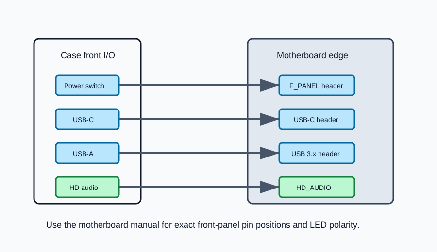
- Locate the motherboard
F_PANELheader at the bottom edge of the board. - Connect the case power switch plug to the
PWpins. Switch polarity does not matter. - Connect reset switch, power LED, or HDD LED plugs only if the case provides them.
- For LED plugs, align positive and negative polarity with the motherboard labels before pressing the connector down.
- Use these verified motherboard header labels:
| Label | Function | Polarity note |
|---|---|---|
PW+ / PW- |
Power switch | Polarity does not matter for a simple switch. |
RES+ / RES- |
Reset switch | Polarity does not matter for a simple switch. |
PLED+ / PLED- |
Power LED | Polarity matters. |
PWR_LED+ / PWR_LED- |
Alternate power LED pins | Polarity matters. |
HD+ / HD- |
Drive activity LED | Polarity matters. |
SPEAK+ / SPEAK- |
Case speaker | Only used if a speaker is supplied. |
CI+ / CI- |
Chassis intrusion | Not used unless the case provides this cable. |
NC |
No connection | Leave unused. |
- Leave speaker and chassis-intrusion pins unused unless the case accessory bundle includes those cables.
- Connect the front USB-A cable to the motherboard USB 3.x header.
- Connect the front USB-C cable to the motherboard USB-C front-panel header.
- Connect the HD audio cable to the front audio header at the lower-left area of the motherboard.
- Check that each keyed connector is aligned before applying pressure.
- Leave a small service loop so connectors are not under tension.
Verification Checklist
Section titled “Verification Checklist”- Power switch is connected to the correct pins.
- LED polarity is correct where LEDs are connected.
- Front USB-A connector is fully seated.
- Front USB-C connector is fully seated.
- HD audio connector is fully seated.
- No header pins are bent.
- Cables are not pulling on the headers.
Common Mistakes
Section titled “Common Mistakes”- Reversing LED polarity and assuming the system is broken.
- Misplacing the power switch plug by one pin.
- Forcing the USB-C connector at an angle.
- Routing HD audio too tightly.
- Forgetting front-panel connectors before first boot.
Expected Result
Section titled “Expected Result”The case power button and front I/O are connected and ready for first boot testing.
Sources Reviewed
Section titled “Sources Reviewed”Next Chapter
Section titled “Next Chapter”Continue to First Boot.